
A 40×80 steel building with an overhead crane only delivers its promised 3,200 ft² of unobstructed lift space if every structural, spatial, and financial decision is locked in before the first anchor bolt is cast: readers will learn how to size the crane's true capacity (dead weight + rigging + 10-15% dynamic buffer), choose single- or double-girder layouts to squeeze every inch of headroom, and place runway columns on a uniform grid with a mid-runway braced bay so thermal and braking forces don't wreck the frame or the budget. The article shows why mounting runway beams directly on main columns saves thousands up to ~100 kN, when independent crane columns are worth the floor space, how tapered or misaligned columns shrink usable bay width, and why 3-D modeling beats flat drawings for catching clearance conflicts early. It walks through OSHA/ISO erection, alignment, and commissioning tolerances–anchor bolts within +/-3 mm, rail elevation within +/-10 mm, and three-stage load testing–that prevent costly rework and long-term wheel wear, then closes with real-world cost layers: $18-$22/ft² for the kit, $4-$10/ft² for foundations, $40k-$100k for the crane, plus 20-30% hidden extras, all of which stay controllable through single-source procurement, early permits, daily cost tracking, and a 10-15% contingency reserved solely for surprises. Master these integrated design, construction, and budgeting steps and you turn a complex crane-integrated project into a predictable, on-schedule asset instead of a field of change orders.
Design Fundamentals for a 40×80 Steel Building with Crane
Lock in your crane specifications and three critical dimensions–lift height, headroom, and c-dimension–before finalizing steel to avoid costly changes after fabrication begins.
Understanding span and load requirements
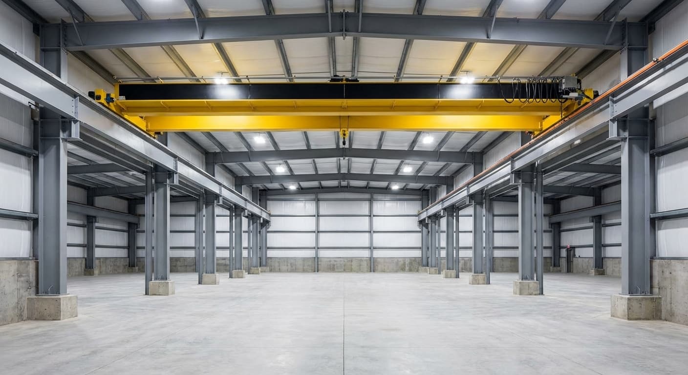
Your 40×80 steel building delivers 3,200 square feet of clear-span space with no interior columns blocking your crane path. [2] That's the beauty of pre-engineered steel–you get maximum operational flexibility right out of the gate. But here's what matters for your bottom line: your building must handle both the crane's dead weight and its maximum working load as one combined force. [1]
This single number determines everything: beam sizes, column requirements, foundation depth. Miss it early, and you're looking at costly change orders and delays. That's why smart operators lock in crane specifications before ordering steel–not after. With proper planning, you can often mount runway beams directly on main columns, eliminating the cost and space requirements of independent crane supports. [1]
Selecting the right crane capacity
Start with your heaviest load, then add every piece of lifting gear–hooks, slings, spreader beams, magnets. They all count against your crane's capacity. [3] Now add 10-15% for safety. Why? Because loads swing. They shift. They generate forces beyond their static weight. Size your crane too tight, and you'll accelerate wear on every component. [3]
Here's what separates working cranes from broken ones: duty cycle classification. A crane lifting twice an hour operates under completely different stress than one running 20 cycles. Get this wrong, and you'll face premature failures regardless of tonnage rating. [4]
Think ahead. If growth is in your forecast, size up one capacity tier now. The incremental cost beats retrofitting beams, columns, and electrical systems when production ramps up. [4] That's the kind of forward thinking that keeps projects on budget long-term.
Integrating clear headroom specifications
Three numbers determine if your crane delivers full value: lift height (floor to hook at maximum), headroom (rail top to lowest obstruction), and c-dimension (trolley surface to hook saddle). [5] Lock these in before finalizing eave height–changing rail elevation after steel goes up blows budgets fast.
Your crane configuration choice directly impacts usable lift within your building envelope. Single-girder cranes place the hoist on the bottom flange, trading lift height for simplicity. Double-girder designs let the trolley run between girders, squeezing extra lift from the same building height–perfect when every inch counts. [5]
Tight on headroom? Low-headroom hoists run parallel to the girder instead of hanging below. Side-mounting girders to end trucks instead of top-mounting gains critical inches. Small changes, big operational impact. [5]
Don't overlook reeving. Heavy-duty 4/1 or 4/2 configurations increase c-dimension, eating into your lift height even with rails at the same elevation. [5] Factor this into eave height calculations now, not when the hook comes up short during commissioning. That's how you keep crane integration smooth and
Strategic Column Placement to Maximize Headroom
Uniform column spacing lets you size runway girders once and repeat them, eliminating individual engineering work for each bay and preventing collision risks.
Analyzing column grid patterns
In a 40×80 building designed from the ground up with a crane, the column grid isn't a background decision–it defines every operational limit the crane will have. Standard portal frame buildings use evenly spaced columns along each sidewall, and that regularity matters because crane runway beams must land on consistent support points. When column spacing is uniform, runway girders can be sized once and repeated, rail joints align predictably with support points, and end trucks travel without encountering clearance conflicts.
Irregular spacing breaks that logic: if runway beam spans vary between bays, each segment requires individual engineering, and end truck travel near tighter bays may create collision risks with column faces or bracket projections that simply don't exist in the uniform layout. [6]The decision between mounting runway beams directly on building columns versus installing dedicated crane columns runs parallel to the grid pattern discussion. For lighter crane loads–generally under 100 kN–runway girders can sit on brackets welded to the primary building columns, keeping the footprint clean and avoiding additional foundations. Beyond that threshold, independent crane columns become the more structurally honest solution because they isolate crane-induced forces from the building frame. [7] The catch is that independent columns must still be analyzed together with the building columns, not separately–lateral displacement of the building frame under wind or crane braking loads can transfer stress into the connection between the two column types if they're treated as isolated systems. [7] In a 40×80 layout, this typically means the crane columns run inside the building envelope parallel to the sidewalls, consuming floor space but creating a clean structural load path.Braced bay placement within the column grid controls how runway girder expansion and longitudinal crane forces are managed along the 80-foot length of the building.
Positioning the braced bay at the midpoint of the runway–rather than at either end–splits thermal expansion in both directions, halving the total movement each end must absorb and reducing the cumulative stress that would otherwise build up in the girder. [7] For a 40×80 building, this places the braced bay roughly at the 40-foot mark along the runway. Columns within that braced bay carry the anchoring function for longitudinal forces from crane acceleration and braking, while columns on either side of it are detailed with slotted connections that allow the runway girder to move freely without inducing bending back into the column. [7] Getting this placement wrong pushes thermal and braking forces toward the end columns, which are already handling vertical runway reactions, and compounds stress at connections that weren't designed for the combined demand.
Balancing structural integrity and crane operation
Tapered building columns introduce a geometry problem that straight columns don't: the column face narrows as it rises, so the usable crane bay width at rail height is meaningfully less than the bay width at the floor. On a tapered column that measures 30 inches at the top, that single column face consumes 30 inches of bay width–two of them across a 40-foot span subtract 5 feet from the crane's effective travel width before anything else is accounted for. [8] Straight columns simplify this by keeping the same face dimension from floor to rail, but they still require measuring the innermost projection on any column flange, since even minor inconsistencies reduce the clearance the end truck has to travel. [8] Separately, floor seam location controls where runway support columns can be anchored, and this is often overlooked until installation.
A seam centered directly under the column line is the cleanest scenario–the base plate and anchors can straddle it symmetrically. Off-center or diamond seams force column offsets or enlarged base plates with anchors spread to avoid drilling too close to the seam, because anchors placed near cracked or seamed concrete create stress risers that propagate further cracking under cyclic crane loads. [8] For tieback connections–where floor-supported crane columns brace laterally against building columns–flange thickness on the building column determines whether a weld is structurally feasible or whether the connection must be redesigned.
Discovering thin flanges during installation rather than during design adds both time and cost, since tieback geometry may need to change entirely. [8] Finally, OSHA requires a minimum 3 inches of clearance above any moving component of the crane system, which means that when the top of the crane bridge is calculated at full travel height, the lowest overhead obstruction–whether a purlin, a conduit, or an HVAC duct–must clear that elevation by at least that margin. [8] Any utility runs planned after crane design is finalized need to be routed with this constraint in mind, since rerouting them post-installation is far more disruptive than coordinating placement upfront.
Using software tools for optimal layout
3D modeling takes the guesswork out of crane placement. You can drop your crane system into a virtual 40×80 building and check everything that matters–headroom clearances, end truck paths, rail-to-obstruction gaps–before ordering steel. [9] Find a runway beam hitting a column bracket in the model? Fix it in minutes. Find it during installation? That's days of delay and structural rework. [9]
Advanced simulation goes deeper. Manufacturing facilities use tools that map complete crane travel paths and flag collision zones between equipment, columns, and worker routes. [10] Your structural engineer gets verified data instead of assumptions–a huge difference when tolerances are tight.
The real value comes from sharing. Export your model to everyone–structural engineer, crane supplier, erector–in the same visual format. No more interpretation errors from flat drawings. Each trade validates their work against the same 3D reference. [9] When you're coordinating
Construction Best Practices and Quality Assurance
Pre-erection communication between your general contractor, erector, and fabricator prevents costly delays and safety issues that a simple coordination meeting catches in minutes.
Pre-erection planning and clear communication
Most crane-related erection problems trace back to conversations that didn't happen before the first steel piece was set. OSHA's steel erection standards treat pre-erection communication as a structural requirement, not a formality–the controlling contractor must issue written notification to the erector confirming site readiness before steel erection can legally begin, and must separately notify the erector in writing before any column is set if anchor rods have been repaired, replaced, or modified. [11] That written exchange exists because anchor bolt discrepancies discovered after a column is positioned require costly remediation that a simple pre-erection check would have caught in minutes. Hoisting operations carry a parallel requirement: every lift must be pre-planned before it happens, with qualified riggers assigned to any operation where workers are exposed to loads overhead. [12] For a 40×80 building with a crane system being installed simultaneously with primary framing, this means the crane supplier's rigging plan and the erector's lift sequence need to be reconciled before either crew arrives on site.Sequencing drives everything else in a steel erection project, and it starts with a meeting between the general contractor, the erector, and the fabricator–in that order.
The general contractor sets the construction direction; the erector determines crane size, bay divisions, and movement sequence based on that direction; the fabricator then sequences shop production to match. [13] If that chain of communication breaks down–or if the fabricator isn't looped in early–steel arrives on site in the wrong order, requiring rehandling that a tight 40×80 lay-down area can't easily absorb. The erector should also confirm during this phase whether interior access is needed and whether the site will physically support the crane during erection, since starting before the site is ready costs the erection team far more than a short delay. [13]A site-specific erection plan formalizes all of this into a document every worker on the project must review before work begins. The plan is developed across pre-construction conferences involving the erector, the controlling contractor, the project engineer, and the fabricator–and it must be signed and dated by the qualified persons responsible for it. [11] For a project with an integrated crane system, the plan should explicitly address the erection sequence for the runway beams and crane columns relative to the primary framing, since those elements have load-path dependencies that affect the order in which bays can be released for occupancy.
Erection drawings within the plan must show the sequence in which the structure is erected, confirm stability at each stage, and document any procedure changes made on-site by a competent person before those changes are used. [13] Distributing the same signed plan to every crew member–and having each one confirm they've read it–creates a common reference that prevents the miscommunication between trades that typically causes delays during installation.
Ensuring quality of steel components and connections
Steel quality failures in crane-integrated buildings rarely announce themselves during fabrication–they surface under load, often after installation makes them expensive to fix. Runway beam alignment is the most tolerance-sensitive element in the system: ISO 12488-1 specifies an elevation tolerance of +/-10 mm between opposing beams, lateral rail deviation of no more than +/-3 mm over any 2-meter length, and a span tolerance of +/-5 mm. [14] Exceeding these limits accelerates wheel flange wear, degrades rail contact, and introduces lateral loads the beam wasn't designed to carry.
Beam-to-column connections must handle both vertical crane loads and lateral forces from acceleration and braking without inducing deformation at the joint–bolted end plates and welded brackets are the standard options, but the choice must reflect the actual load path rather than fabrication convenience. [14] Rail fastening method matters independently: elastically fastened rails using pads reduce vibration and noise transmission into the structure, welded rails are fixed permanently but eliminate adjustment, and bolted clip systems allow realignment if tolerances drift after initial installation. [14]Before any crane moves under load, OSHA requires that all new and altered cranes be inspected to confirm compliance–this isn't optional and it isn't satisfied by a visual walkthrough. [15] The commissioning sequence that satisfies this requirement runs in three phases: a no-load trial that confirms all mechanical and electrical components function correctly under self-weight, a static full-load test that verifies the structure holds rated capacity without measurable deflection beyond allowable limits, and a dynamic movement test that introduces acceleration, deceleration, and travel to surface issues that static tests miss. [15] Each phase generates documented results that must be compared against acceptance criteria, and any failed item goes on a punch list before final acceptance is granted. [15] OSHA's inspection framework separates ongoing inspection into two categories–frequent inspections on a daily to monthly cycle, and periodic inspections on a 1-to-12-month cycle–with the specific interval tied to the component's exposure to wear and the crane's duty cycle. [16] Upper limit switches must be tested under no load at the start of each operator shift, inching the block in slowly rather than running it to the limit at full speed. [16] These aren't bureaucratic checkboxes; they're the mechanism that surfaces fatigue cracks, loose fasteners, and rail drift before they compound into structural failures. Keeping inspection records on file for the life of the equipment–as CMAA 78 and ASME B30.2 require–gives future engineers and inspectors a documented baseline to measure change against rather than starting from scratch each time. [15]
Service-focused inspection checkpoints
Owner-driven inspection catches what contractor QC misses–not because contractors cut corners, but because an independent set of eyes looking at finished work surface problems that in-progress crews normalize.
For a 40×80 building with an integrated crane, three structural checkpoints carry the most consequence.
First, anchor bolts: each bolt should sit within +/-3mm of its specified position, with no more than 3mm of deviation over any 300mm of bolt length, and the foundation surface beneath base plates should be level within 3mm over every 3 meters. [17] Second, column plumb: an acceptable tolerance is 1/500 of column height–roughly 6mm for a 3-meter column–measured on both major and minor axes, not just the face visible from the floor. [17] Third, connections: every bolted joint needs at least 1.5 to 2 thread lengths projecting beyond the nut, and welded joints should be visually clear of cracks, undercut, and porosity before any load is applied. [17] Beyond these structural checkpoints, non-destructive testing closes the gap between what a visual inspection can confirm and what actually determines long-term reliability–ultrasonic and magnetic particle testing reveal subsurface cracks and inclusions that look fine on the surface but propagate under cyclic crane loads. [18] Every inspection result, whether a passed weld or a flagged anchor bolt, belongs in a centralized record alongside the mill certifications and material test reports; digital documentation platforms let project managers track open issues in real time and give future engineers a verified baseline rather than assumptions when the building is modified or the crane is upgraded. [18]
Cost Management and Single-Source Solutions
Single-source procurement eliminates coordination gaps that typically create delays, mismatched specifications, and conflicting accountability across separate building, crane, and runway suppliers.
Estimating total project cost for 40×80 building with crane
Your 40×80 steel building with integrated crane involves three cost layers that most quotes split apart. The building kit runs $18-$22 per square foot–that's $57,600 to $70,400 for your 3,200-square-foot space. Need extra headroom for crane clearance? Each additional two feet of height adds $3,000-$7,000 to your steel package. [19] Foundation work comes next at $4-$10 per square foot, rarely included in kit pricing. Your concrete slab will cost $12,800-$32,000 depending on soil conditions and local labor. [19][20] Construction and installation add another $5-$10 per square foot. Total building cost before the crane: $86,400 to $128,600. [19]
The crane itself breaks down this way:
- Single-girder bridge crane: starts at $40,000
- Double-girder system: $65,000-$100,000 (better for maximum lift in tight eave heights)
- Neither price includes runway beams or installation [21]
Runway structure costs vary dramatically. If your building columns can carry crane loads directly, you save thousands. Need independent crane columns? Budget for extra steel, labor, and dedicated foundations not shown in standard quotes. [21]
Don't forget the hidden 20-30% that catches most budgets off-guard:
- Site preparation and grading
- Drainage systems
- Utility connections
- Permit fees specific to crane-rated foundations [19]
Smart move: Add 10-15% contingency to your total. When crane specs, foundation depth, and column placement all depend on each other, changes ripple through your budget fast. [20]
Leveraging single-source procurement for efficiency
Splitting a crane-integrated steel building across multiple suppliers–one for the building kit, one for the crane system, one for runway beams–creates a coordination gap that shows up as delays, mismatched specifications, and conflicting accountability when something goes wrong during installation.
Single-source procurement eliminates that gap by placing the entire building envelope under one supplier's responsibility: components arrive bundled, labeled, and matched to a single packing list, and any missing or damaged piece has one clear resolution path rather than a dispute between vendors over whose scope it falls under. [22] That accountability structure also simplifies the technical handoff–when the building designer and the crane system designer are the same entity, headroom calculations, column bracket sizing, and runway beam spans are resolved internally before anything ships, rather than being negotiated between separate engineering teams after fabrication is already underway. [24] Suppliers that offer integrated crane building design–handling structural brackets, runway beam coordination, and crane type selection alongside the primary framing–compress the design timeline by removing the back-and-forth that typically adds weeks to projects where building and crane engineers work from independent drawings. [24] One cost-reduction lever worth specifying early in this conversation: overhead cranes built from box girders rather than wide-flange structural beams offer lower weight, greater design flexibility, and in some configurations, reduced runway beam loading–all of which can compress structural requirements and bring material costs down on the building side as well as the crane side. [23]
Problem-solving tips to avoid common budget overruns
Budget overruns on crane buildings follow predictable patterns. Here's how to dodge them: Stop treating costs as separate line items. Your building kit, crane system, and site work are interconnected. Change your crane capacity? Foundation depth changes. Switch column types? Runway costs shift. Budget these as one unified system, not three separate projects.
Implement formal change orders from day one. Every modification to crane capacity, eave height, or column placement ripples through multiple trades. Without documented pricing approved before work continues, those "small" changes compound into major overruns. Track every adjustment with written approvals and updated pricing. [26]
Start permits and procurement early–especially for crane buildings. Crane-rated foundations need extra engineering review beyond standard building permits. Start late and you'll compress your schedule while material prices climb. Submit structural drawings 4-6 weeks before you think necessary. [27]
Track costs in real time, not monthly. Catch a runway beam span change during procurement? That's a negotiation. Discover it during erection? That's a delay with compounding labor costs. Daily tracking turns surprises into manageable adjustments. [27]
Invest in thorough site assessment before breaking ground:
- Complete soil testing (not just spot checks)
- Map existing utilities precisely
- Review drainage patterns
- Identify access constraints
Generic estimates miss these site-specific realities that later require expensive fixes. [27]
Keep contingency funds separate and untouchable. Budget 5-10% above your calculated total, but don't let it get absorbed into the base scope. This buffer handles the inevitable field adjustments without derailing your project. Mark it clearly: "For unforeseen conditions only." [25]
- Lock in crane specs before ordering steel to avoid costly change orders and delays.
- Uniform column spacing prevents custom runway beams and collision risks during crane travel.
- Mid-runway braced bay halves thermal expansion stress and keeps longitudinal forces off end columns.
- OSHA mandates 3 in. clearance above every moving crane part–route utilities before finalizing eave height.
- Single-source procurement bundles building, crane, and runway under one supplier to eliminate scope gaps.
- Daily cost tracking turns span changes into negotiations, not expensive erection-day surprises.
- Box-girder cranes cut weight and runway loads, trimming both crane and building steel costs.
- https://www.braemarbuildings.com/metal-crane-buildings.php
- https://www.buildingsguide.com/standard-sizes/40×80-metal-building/?srsltid=AfmBOoqEoraC3mqdg4TaxfXvy6r_K84ZY_AbDc078yZRBj2xnCLZB5S3
- https://www.yuantaicrane.com/news/determine-required-capacity-of-overhead-cranes.html
- https://www.bettercrane.com/resouces/news/crane-tonnages.html
- https://www.demagcranes.com/en-us/understanding-lift-height-for-your-next-overhead-crane-project
- https://jsbwcrane.com/overhead-crane-selection-guide-for-existing-factories-headroom-columns-roi/
- https://fgg-web.fgg.uni-lj.si/~/pmoze/esdep/master/wg14/l0400.htm
- https://www.mazzellacompanies.com/learning-center/overhead-crane-quote-expectations/
- https://titansteelstructures.com/metal-structure-tutorials/how-to-design-a-manufacturing-facility-with-our-3d-building-design-tool/
- https://www.bettercrane.com/resouces/news/multi-overhead-crane.html
- http://www.osha.gov/etools/steel-erection/site-preparation
- http://www.osha.gov/etools/steel-erection/inspection-guide
- https://stevensec.com/blog/best-steel-erection-practices
- https://vocal.media/journal/overhead-crane-runway-beam-design-standards
- https://www.yuantaicrane.com/news/overhead-crane-commissioning-checklist.html
- http://www.osha.gov/laws-regs/regulations/standardnumber/1910/1910.179
- https://ztsteelstructure.com/steel-construction-quality-checklist-10-key-owner-inspection-points/
- https://henryhconstruction.com/structural-steel-qa-qc-checklist/
- https://chinasteelbuildsales.com/40×80-metal-building-cost/
- https://qebuildings.com/2025/10/how-much-does-a-40×80-metal-building-cost/?srsltid=AfmBOorD_rCfLbJ3w7xhTarCHg7FCnKzJlLFTFoKtgOjl3y11cIAA0tw
- https://www.mazzellacompanies.com/learning-center/what-is-the-cost-of-an-overhead-crane/
- https://norsteelbuildings.com/us/advantages-of-steel-series/advantages-single-source-responsibility/
- https://www.ghcranes.com/cranes/minimize-your-steel-building-costs-with-overhead-cranes-built-from-box-girders/
- https://www.metalbuildingoutlet.com/crane-buildings/
- https://www.rsmeans.com/resources/mitigating-cost-overruns?srsltid=AfmBOor_WMk8igbjUbtxGfvGOpG2zGpKrSp8qJHJO8JXzan67ZO3ncEz
- https://www.trybeam.com/resources/construction-cost-overruns
- https://www.sage.com/en-us/blog/construction-project-cost-overruns/