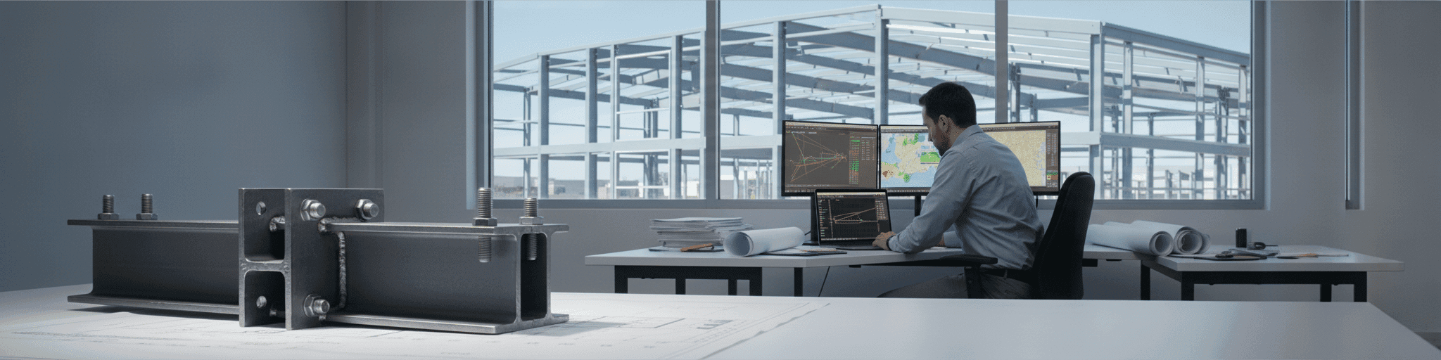

We help you understand how load calculations, site conditions, and building use drive every steel framing component in your structure. Getting these three factors right upfront ensures your building holds up safely and stays on budget, without costly revisions or field problems later.
Why Structural Design Specs Matter Before You Order Steel Framing Components
Wrong geographic assumptions mean steel framing designed for one region won't safely handle another's snow, wind, or seismic forces.
How load calculations, site conditions, and intended use drive component selection
Every steel framing component in your building starts as a number on an engineer's load sheet. Certified engineers calculate dead loads, live loads, snow, wind, and seismic forces specific to your site's postal code, then combine them using code-defined formulas like ASCE 7 to see how the structure behaves under simultaneous stress, wind during a snowstorm, for instance, or equipment weight during peak occupancy [1]. Get the geographic assumptions wrong, and a design built for one region simply won't hold up in another with heavier snow or higher wind exposure [1].
Site conditions layer on additional variables: coastal exposure drives corrosion-resistant coatings and reinforced anchoring, while inland sites may trade wind concerns for higher snow accumulation or seismic risk [1]. Intended use matters just as much. A warehouse floor absorbing forklift traffic carries a different live load than an office floor, and that difference changes beam size, grade, and connection detail before fabrication ever begins [2].
Component selection follows directly from these three inputs working together [3].
What happens when design specs are overlooked: real cost and safety consequences
Skip the load math and the failure shows up later, sometimes catastrophically.
Two metal agricultural warehouses built for cottonseed storage bulged outward and cracked their floor slabs once loaded to the roofline, because designers never calculated the outward pressure stored product exerts on warehouse walls, a force standard soil mechanics equations predict reliably.[4] In another documented case, cold-formed steel beams supporting a concrete deck collapsed mid-pour, injuring four workers, after the engineer skipped calculations for unbalanced load combinations specific to cold-formed sections rather than hot-rolled steel.[4] Beyond acute collapse, steel structure failure often develops gradually: corrosion, fatigue, and overloading weaken connections over months or years until a structure can no longer safely carry its design loads, sometimes without visible warning.[5] Humid regions carry particularly high corrosion risk for structural steel components left unspecified for the environment.[5] The financial fallout compounds the safety risk: repair, remediation, litigation, and downtime costs routinely dwarf what proper load and site analysis would have cost upfront.[5]
How National Steel Buildings integrates design specs into every custom quote
Your custom quote starts with real numbers, not guesswork. We treat quoting as a technical conversation first: before pricing, we gather your site location, intended use, occupancy loads, and environmental exposure so the load calculations behind your quote reflect your actual building, not a generic template [6]. That upfront work matters because accuracy scales with information quality.
The more complete your site and use-case details, the tighter your quote and the fewer revision cycles later [6]. We separate requests into modified-standard versus full-custom tracks during feasibility review, catching mismatched specs before fabrication starts rather than after steel is cut [7]. Your quote reflects that feasibility assessment: we check code compliance, structural viability, and whether standard steel framing components meet your load and site profile, or whether custom-engineered members are required [7].
That review happens before drawings finalize, so the number you receive already accounts for the load, corrosion, and use-case variables specific to your project, not a rough estimate revised later. That's single-source accountability, every step of the way.
The Three Core Design Factors: Load, Site Conditions, and Building Use
Design steel components for both dead load and live load combined, since sizing against either one alone leaves your structure vulnerable to real-world conditions.
Dead load vs. live load: why both matter for steel framing component sizingDead load covers the permanent weight a steel frame carries every day: the beams, columns, purlins, roofing, and fixed equipment bolted to the structure.[8] Engineers calculate this weight per element, whether it's a line load on a beam or a point load on a column, because it never changes over the building's life and sets a fixed baseline for component sizing.[8] Live load is the opposite: transient, variable weight from people, stored inventory, vehicles, or snow drift that shifts hour to hour.[9] Because live loads are unpredictable, codes require engineers to design for a maximum that far exceeds typical use, with ASCE 7's minimums often 30% higher than what a structure actually experiences over its lifespan.[9] Sizing a column or beam against dead load alone leaves no margin for forklift traffic, roof snow, or crowd loading, and sizing against live load alone ignores the steel's own weight stacking up floor by floor.
Component capacity has to account for both combined, the code-defined "gravity load," before a single beam gets cut.
Environmental site factors that determine corrosion resistance and material grade
Use-case requirements: agricultural, aviation, commercial, industrial, and religious applications need different component specs Building use dictates component specs as much as load numbers do. Agricultural and industrial facilities often need hybrid framing or crane-ready primary members, since crane runway beams, rails, and structural supports have to tie directly into the frame rather than bolt on afterward once equipment loads are known [12].
Our agricultural steel buildings are engineered around those working loads from the start. Aviation hangars flip the equation entirely: clear-span width has to clear the aircraft wingspan plus 4 to 8 feet of ground-movement clearance per side, and eave height has to clear the tail plus 3 to 5 feet of working room, numbers no warehouse or sanctuary shares.
Commercial buildings generally run standard rigid-frame systems sized for occupancy and appearance rather than equipment weight, while religious buildings borrow that same commercial framing but often add steeper rooflines or steeple loads that shift wind and snow calculations [12]. For hangar bays and FBO facilities, door type and tail clearance drive frame design as much as wingspan itself.
Essential Steel Framing Components and Their Design Specifications
Deeper beam sections cut member weight by 25 percent, while shallow sections cost 60 percent more steel to meet the same design criteria.
Primary load-bearing members: columns, beams, and trusses–what specs control their capacity
Column, beam, and truss capacity comes down to span, load, and section depth working together, not steel grade alone. AISC's preliminary sizing tables map wide-flange beam depth ranges across spans from 15 to 45 feet under three live-load conditions, with matching girder depths for bay sizes up to 45×45 feet [14].
Depth and weight trade off directly: dropping a beam one nominal size deeper cuts member weight roughly 25 percent, while forcing a shallower section into the same span can add 60 percent more steel to hit the same design criteria [14]. That tradeoff is why a tighter footprint spec often costs more in tonnage, not less.
Underneath these depth charts sits the AISC allowable-stress framework, which sets the actual stress limits every wide-flange section, column, or truss chord has to meet before a size gets approved [15]. The Steel Construction Manual compiles the full specifications and codes governing this design, fabrication, and erection process in a single reference [16].
Secondary framing: purlins, girts, and bracing–how design specs prevent deflection and lateral movement
Purlins and girts are the secondary steel framing components that catch load before it ever reaches the primary frame. Girts run horizontally between columns to brace walls laterally, while purlins do the same job along the roof, transferring cladding, wind, and snow loads back to the rafters and columns [17]. Most are cold-formed C- or Z-shaped profiles, sized initially using a depth-to-length ratio of roughly 1/32, then checked against bending, shear, and deflection [17].
Deflection is the real design constraint here: codes commonly cap secondary members at L/180, meaning a purlin can flex only so far before cladding cracks or fasteners loosen [17]. Because cold-formed Z-sections offer a high strength-to-weight ratio, they're also prone to twisting or local buckling under load if left unbraced [17]. That's where sag rods come in, typically 10-12mm steel struts installed between purlins to hold alignment and resist the tendency to bend or rotate under wind and snow [17].
Skip that bracing detail and you're relying on the panel skin to do a structural job it was never spec'd for.
Fasteners, connections, and decking: why spec compliance here prevents catastrophic failure
Connections are where design intent meets field tolerance, and small deviations here carry outsized consequences. Bolt hole dimensions can't just be close: AISC Specification Table J3.3 caps standard, oversized, and slotted hole sizes, and any hole exceeding those limits must be treated as the next larger classification, changing the bearing and slip calculations an engineer already signed off on [18].
High-strength bolts have to match AISC, RCSC, and ASTM requirements specifically so a bolt failure shows up as a torque-tension fracture in the shank rather than a thread-stripping failure, a distinction that determines whether a connection fails predictably or catastrophically [18]. Connection type matters too.
Simple, nominally pinned connections are engineered to transmit shear only, with negligible rotational resistance, and swapping in a non-standard connection detail without re-checking that classification can quietly overload a joint never designed to carry moment [19]. Revised RCSC provisions also govern hot-dip galvanized structural connections, since coating thickness and surface prep directly affect bolt pretension and slip resistance [20].
How to Work with National Steel Buildings to Get Design Specs Right the First Time
Verify anchor bolt patterns against steel column base plates before erection to avoid costly field rework that derails your project timeline.
The design consultation process: how NSB engineers translate your site and use case into component specifications
Your consultation follows the same sequence engineers use on any structural project, just compressed into a single conversation instead of months of separate meetings. It starts with conceptual review: matching your site's soil type, environmental exposure, and spatial needs against feasible foundation and framing options before anything gets drawn [21].
From there, engineers move into load analysis, quantifying dead loads, live loads, and site-specific wind, seismic, and snow forces using ASCE 7-22 combinations, then run structural analysis to check how your proposed frame responds to those forces [21]. System design comes next: choosing between frames, trusses, or shear walls based on your building's actual function, since a warehouse and a hangar demand different support strategies for the same square footage [21].
Element detailing then converts those choices into dimensioned, connection-ready specs before fabrication starts [21].
From spec sheet to erection: how ProTrades ensures components are installed to design intent
Design intent doesn't survive erection by accident.
Field crews translate engineer-approved shop drawings into physical structure by verifying anchor bolt patterns against steel column base plates before columns ever get set, since a mismatch here forces costly field rework later.[22] OSHA's steel erection standard reinforces that discipline, defining exact requirements for column anchorage, connector work, and structural steel assembly so components go up the way the design intended rather than however a crew finds convenient.[23] Small dimensional variations in fabricated members accumulate across a frame, and the AISC Code of Standard Practice ties fabrication tolerances directly to field fit-up quality for that reason.[24] Weld quality checks, connection inspections, and pre-fabrication meetings between supplier and erector catch misalignment before it becomes a structural liability.[22] That coordination between engineering, fabrication, and erection crews is what keeps a spec sheet's numbers intact all the way through the final bolt.[24]
Your design spec Essentials: what information to gather before contacting National Steel Buildings
Before you pick up the phone, assemble the same inputs we need to move your project from a rough range to a number you can budget around. Vague requests get hedged estimates; specific ones get engineered quotes.
- Building dimensions: width, length, eave height, roof pitch
- Site location: city, state, ZIP for wind, snow, and seismic data
- Intended use, described specifically rather than generically
- Foundation plan and site condition, including any survey or geotechnical report
- Local code amendments: county wind or seismic overlays, hurricane zones, fire separation distance
A vague description like 'commercial building' leaves floor loads, door sizing, and occupancy classification undefined, while a specific use case is engineering-ready from the first call. Skipping local code data is the costliest gap: a quote missing county amendments often returns fast but fails permitting, costing weeks in re-engineering.
Get those inputs in front of us and the rest is on us. We handle the load math, code compliance, fabrication, and erection through our in-house ProTrades crews, so your project stays single-source, on schedule, and within budget. Tell us your site and use case, and we'll turn them into a building spec that holds up the first time. Get a Free Quote and we're with you every step of the way.
- Structural design requires three core inputs: dead loads, live loads, and site-specific conditions like wind, snow, and seismic forces calculated by postal code.
- Building use directly determines component specifications; agricultural facilities need crane-ready members while aviation hangars require clear-span widths exceeding aircraft wingspan by 4-8 feet.
- Beam depth and weight trade off inversely: going one size deeper reduces member weight by 25%, while forcing a shallower section adds 60% more steel for the same span.
- Secondary framing like purlins and girts must include sag rod bracing to prevent twisting and local buckling; deflection limits cap at L/180 to prevent cladding damage.
- Connection bolt hole dimensions and specifications directly impact bearing calculations and slip resistance; non-standard holes must be reclassified, changing the entire connection design.
- Fabrication tolerances accumulate across frames; coordination between engineering, fabrication, and field crews prevents dimensional mismatches that force costly rework.
- Incomplete project information produces hedged estimates that fail permitting; specific details about site location, use case, and local code amendments enable accurate engineered quotes.
- https://norsteelbuildings.com/us/building-codes-permits/steel-building-codes-loads/
- https://highcountrymetalworks.com/post/steel-load-calculation
- https://ibarraconstructionservices.com/mastering-structural-steel-framing-for-metal-buildings/
- https://engr.charlotte.edu/asce-failure-case-studies/building-failure-cases/
- https://structural-innovations.com/what-is-a-steel-structure-failure-how-its-detected-and-remedied/
- https://www.synthx.com/an-engineering-quote-for-your-project/
- https://khindustries.com/blog/kh-industries-custom-engineering-process/
- https://structuralbasics.substack.com/p/the-dead-load
- https://mtcopeland.com/blog/live-load-vs-dead-load-vs-environmental-load-differences/
- https://www.aisc.org/bridges/bridge-resource-center/corrosion-protection-and-durability-resources/
- https://www.corrosionlab.com/how-a-corrosion-testing-service-helps-select-the-right-materials
- https://rapidsetbuildings.com/metal-buildings/industrial/
- https://www.aisc.org/architecture-center/resources/engineering-basics/preliminary-beam-girder-and-column-size-tables/
- https://docs.bentley.com/LiveContent/web/STAAD.Pro%20Help-v17/en/GUID-0C55CE35-2DFF-4A4D-8560-258ADDACB399.html
- https://www.aisc.org/aisc/publications/steel-construction-manual/
- https://www.calctree.com/resources/purlins-n-girts
- https://www.aisc.org/aisc/solutions-center/engineering-faqs/5-connections/
- https://steelconstruction.info/topics/design/simple-connections/
- https://www.hotdipgalvanizing.com/technical-resources/2020-rcsc-specification-revision-cost-saving-changes-for-hot-dip-galvanized-structural-connections
- https://www.existingconditions.com/insights/what-is-the-step-by-step-process-of-structural-design
- https://iconsteelbuildings.com/construction-quality-control-checklist/
- http://www.osha.gov/enforcement/directives/cpl-02-01-034
- https://wasinc.com/structural-steel-fabrication-industrial-facilities/